高电压小电流试验机(耐电弧试验仪)主要技术要求
1、输入电压: 交流 220 V
2、输出电压: 交流 0--20 KV ;
3、电器容量: 1.5 KVA
4、试验方式: 间歇电弧,连续电弧
5、试验电流: 10MA-20MA-30MA-40MA可选
6、试验电压控制误差: ≤ 1%
7、电弧通断时间误差: <5ms
8、试验电压连续可调: 0--20 KV
9、电极规格:不锈钢板状电极 25.4mm*12.7mm*0.15mm
钨钢电极 56mm*7mm*30mm
电极配置角110度
电极重量:50G
10、安全防护措施:(1)超压保护
(2)过流保护
(3)短路保护
(4)安全门开启保护
(5)软件误操作保护
高电压小电流试验机(耐电弧试验仪)主要配置
1、试验主机一台
2、2万伏高压发生器一台
3、全自动微电脑电压调压装置一套(串口方式)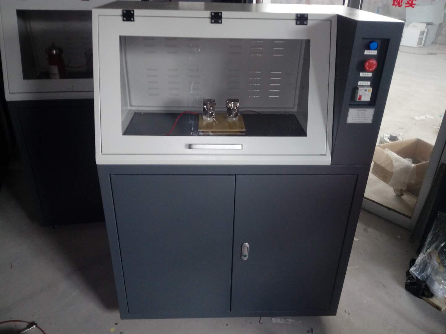
4、电压采集及电流采集隔离式变送装置一套
5、试验电极:两套
6、放电棒一只(树脂式)
仪器是按照GB1411 、IPC650、IEC61621、ASTMD495设计制造,并符合JEC149、UL746A等试验方法。应用于电机、电器和家用电器等行业的电工用塑料、树脂胶和绝缘漆等绝缘材料的耐电弧性能评定。主要适用于固体绝缘材料如:塑料、薄膜、树脂、云母、陶瓷、玻璃、绝缘油、绝缘漆、纸板等介质的耐电弧性能测试;本试验机采用计算机控制,试验过程中可在线观察试验曲线;自动存储试验条件及试验结果等数据,并可存取、显示、打印.
是针对电缆电线行业关于电线耐电弧试验而生产的一款检测设备。依据检测标准,可以方便检测出电线的耐电弧特性,操作简单,测试过程*自动化进行,无需人工操作。试验过程参数可以通过软件设定保存,试验过程计算机自动化控制,试验结束后,自动停止并保存试验数据。并可通过打印机打印出完整试验参数的报告单。
太阳能电池板耐电弧专为太阳能电池板耐电弧试验的试验机,采用电子式控制,试验过程中可在线观察弧光烧灼情况及当前电压及电流等参数变化,试验时间可自由设置等。
一、高电压小电流试验机(耐电弧试验仪)范围本标准叙述的试验方法能够提供同类绝缘材料当其被暴露于高电压、小电流电弧放电时,它们之间耐受发生在紧靠表面损坏情况的初步差异。电弧放电引起局部热的和化学的分解与腐蚀并终在绝缘材料上形成导电通道。试验条件的严酷程度是逐渐增加的:开始几个阶段,小电流电弧放电反复中断,而到了后来几个阶段,电弧电流逐级增大。二、高电压小电流试验机(耐电弧试验仪)规范性引用文件下列文件中的条款通过本标准的引用而成为本标准的条款。凡是注日期的引用文件,其随后所有的修改单(不包括勘误的内容)或修订版均不适用于本标准,然而,鼓励根据本标准达成协议的各方研究是否可使用这些文件的版本。凡是不注日期的引用文件,其版本适用于本标准。三、定义下列定义适用于本标准。3.1注2:对某些材料,在电极间电弧全部熄灭前,在相当长的时间范围内,朝失效发展的趋势增加,仅当所有电弧已熄灭才发生失效。3.2耐电弧 arc resistance从试验开始直至试样失效的总时间,秒。四、设备4.1试验回路试验设备电气回路的主要部件如图1所示。注:次级回路接线杂散电容应小于40pF。大的杂散电容可能会干扰电弧的形状并影响试验结果。4.1.1变压器,TV该变压器的额定次级电压(开路)为15kV,额定次级电流(短路)为60mA,线路频率为48Hz~62Hz。4.1.2可变比自耦变压器,TC额定容量为1kVA且与线路电压匹配。注:推荐初级电压电源变化保持?2%。4.1.3电压表,VLAC电压表,其准确度为?0.5%,能读出电源电压的

%。4.1.6抑制电阻器,R3额定电阻为15kΩ?1.5kΩ并至少24W。该电阻器与电感(见4.1.7)一起用作抑制电弧电路中的寄生高频。4.1.7空芯电感器,X3,1.2H~1.5H注:用单个线圈构成的这种电感器是不实用的,令人满意的电感器是将导线绕在直径约12.7mm和内长15.9mm的绝缘非金属芯子上的8个3000匝~5000匝的线圈串联而成。4.1.8断电器,B由电机驱动或电子仪器操作的断续器是用作按表1的预定程序进行切断和接通初级回路,以便获得该试验的三个较低阶段所需要的周期。断续器的准确度为?0.008s。4.1.9计时器,TT秒表或电动计时器,准确至?1s。4.1.10接触器,CS当罩在电极装置上的通风防护罩降至设定位置时,该通风防护罩触动常开(NO)微型开关,而微型开关又使接触器CS动作并将变压器TV与回路接通,使得高压HV施加于电极上。当通风防护罩升起时,变压器断开,操作者得到保护。4.2电极和电极装置4.2.1电极电极由直径2.4mm?0.05mm无裂纹、凹痕或粗糙疵点的钨棒制成。活动电极长至少20mm。推荐将这个活动电极固定于把柄上,使得在削尖后的电极能准确定位。该电极应经研磨抛光,以形成与轴线夹角为30??1?的平椭圆面。图2展示出固定于合适把柄上的电极的一个实例。注1:已发现钨焊条是适用于这种电极的。注2:在削尖过程中,采用钢制夹紧装置夹持电极,有助于保证将尖头电极加工成所要求的几何形状。4.2.2电极装置该装置提供了一种夹持电极和试样的方法,使得电弧按正确的角度施加于试样的上部表面。该装置应这样构成,使得每一个试样上部表面在每一次试验时都处在同一高度上。应调节每一电极,使得它以0.5N?0.05N的力无约束地静置于试样上。不应对试样进行抽风,只有当试验过程中试样释放出烟雾或气体时,才允许把这些燃烧产物排放掉。从略高于试样的平面位置,应提供观察电弧的清晰视域。注:对气流的要求,正在考虑之中。4.2.3清洗和削尖电极4.2.3.1清洗电极a)每一次试验后,应该用不起毛的实验室用的纸巾蘸以丙酮或乙醇之类溶剂清洗电极,再用去离子水擦洗电极,然后用干净的、干的不起毛的纸巾将其擦干。4.3试验箱为防止通风,试验箱应是不通风的密闭箱,其尺寸不小于300mm?150mm?100mm。4.4校准4.4.1开路工作电压开路状况下,将电压调节至12.5kV。根据开路的初级电压对次级电压的比,用电压表VL测量该电压。五、试样5.1对材料作正规比较时,应在每一材料的试样上至少做5次试验。六、条件处理除另有规定外,试样应在23℃?2℃、50%?5%相对湿度(按IEC 60212中的标准大气B)标准大气中至少暴露24h。七、程序观察起始电弧以便确定它是否仍然保持平的且紧靠试样表面。如果电弧顶部处于试样表面上方约2mm或者电弧爬向电极上方而不再保持在电极处或者发生不规则的闪烁,则表明回路常数不正确或者材料正在以及大速率释放出气体产物。八、结果8.1本试验的结果是以秒表示的失效时间。注:许多材料常常是在严酷程度发生变化后的开头几秒内失去抵抗能力的。当对材料的耐电弧作比较时,两者差异处于两个阶段交替的那几秒要比处于单个阶段内所经过的相同的那几秒时间重要的多。因此,耐电弧在178s与182s之间和耐电弧在174s与178s之间两者存在着很大的差异。8.2已经观察到的四种通常失效类型8.2.1由于许多无机电介质变成白热状态,致使它们变成能够导电。然而,当冷却时,它们又恢复到其原先绝缘状态。8.2.2某些有机复合物突然发生火焰,但在材料内不形成明显的导电通道。8.2.3另外一些材料可见到因漏电起痕而导致失效,即当电弧消失时,在电极间形成一条细金属丝似的线。8.2.4第四种类型是表面发生碳化直至出现足够的碳而形成导电。
试验过程描述
过程 弧电流/mA 通断时间/秒 持续时间/秒 试验所经时间/秒
1/8-10 10 1/4s通 7/4s断 60 60
1/4-10 10 1/4s通 7/4s断 60 120
1/2-10 10 1/4s通 7/4s断 60 180
10 10 导通 60 240
20 20 导通 60 300
30 30 导通 60 360
40 40 导通 60 420
Main technical requirements
1. Input voltage: AC 220V
2. Output voltage: AC 0-20 KV;
3. Electrical capacity: 1.5 KVA
4. Test method: intermittent arc, continuous arc
5. Test current: 10MA-20MA-30MA-40MA optional
6. Test voltage control error: ≤ 1%
7. Arc on-off time error:<5ms
8. Continuous adjustable test voltage: 0--20 KV
9. Electrode specification: Stainless steel plate-shaped electrode 25.4mm * 12.7mm * 0.15mm
Tungsten steel electrode 56mm * 7mm * 30mm
Electrode configuration angle 110 degrees
Electrode weight: 50G
10. Safety protection measures: (1) Overpressure protection
(2) Overcurrent protection
(3) Short circuit protection
(4) Security door opening protection
(5) Software misoperation protection
Main configuration
1. One experimental host
2. One 20000 volt high voltage generator
3. A set of fully automatic microcomputer voltage regulating device (serial port mode)
4. One set of voltage acquisition and current acquisition isolated transmission device
5. Test electrodes: two sets
6. One discharge rod (resin type)
The instrument is designed and manufactured in accordance with GB1411, IPC650, IEC61621, ASTMD495, and complies with test methods such as JEC149 and UL746A. Evaluation of arc resistance performance of insulation materials such as plastics, resin adhesives, and insulating paints used in the electrical, electrical, and household appliance industries. Mainly suitable for testing the arc resistance performance of solid insulation materials such as plastics, films, resins, mica, ceramics, glass, insulation oil, insulation paint, cardboard and other media; This testing machine is computer-controlled, and the test curve can be observed online during the testing process; Automatically store test conditions and test results data, and can access, display, and print them
It is a testing equipment produced for the cable and wire industry regarding wire arc resistance testing. According to the testing standards, it is easy to detect the arc resistance characteristics of wires, with simple operation and automated testing process, without the need for manual operation. The parameters of the experimental process can be saved through software settings, and the experimental process is automatically controlled by the computer. After the experiment is completed, it will automatically stop and save the experimental data. And a complete report of the test parameters can be printed out through a printer.
The solar panel arc resistance test machine is specially designed for solar panel arc resistance testing. It adopts electronic control and can observe the arc burning situation and changes in current voltage and current parameters online during the test process. The test time can be freely set.
1、 Range of high voltage and low current testing machine (arc resistance tester)
The test method described in this standard can provide preliminary differences in the tolerance of similar insulation materials to surface damage when exposed to high voltage, low current arc discharge.
Arc discharge causes local thermal and chemical decomposition and corrosion, ultimately forming conductive channels on insulating materials. The severity of the experimental conditions gradually increases: in the initial stages, the low current arc discharge is repeatedly interrupted, and in the later stages, the arc current increases step by step.
2、 Normative reference document for high-voltage low current testing machine (arc resistance tester)
The clauses in the following documents become clauses of this standard by reference. Any referenced document marked with a date shall not be subject to any subsequent amendments (excluding errata) or revisions to this standard. However, parties to agreements based on this standard are encouraged to study whether versions of these documents can be used. Any referenced document without a date shall be subject to the version specified in this standard.
3、 Definition
The following definitions apply to this standard.
three point one
Note 2: For certain materials, the trend towards failure increases over a considerable period of time before all arcs between the electrodes are extinguished, and failure only occurs when all arcs have been extinguished.
three point two
Arc resistance
The total time from the start of the experiment until the failure of the specimen, in seconds.
4、 Equipment
4.1 Test Circuit
The main components of the electrical circuit of the experimental equipment are shown in Figure 1.
Note: The stray capacitance of the secondary circuit wiring should be less than 40pF. Large stray capacitance may interfere with the shape of the arc and affect the test results.
4.1.1 Transformer, TV
The rated secondary voltage (open circuit) of the transformer is 15kV, the rated secondary current (short circuit) is 60mA, and the line frequency is 48Hz~62Hz.
4.1.2 Variable ratio autotransformer, TC
The rated capacity is 1kVA and matches the line voltage.
Note: It is recommended to maintain a variation of ? 2% in the primary voltage power supply.
4.1.3 Voltage meter, VL
The AC voltmeter has an accuracy of ? 0.5% and can read% of the power supply voltage.
4.1.6 Suppressing resistors, R3
The rated resistance is 15k Ω? 1.5k Ω and at least 24W. This resistor, together with the inductor (see 4.1.7), is used to suppress parasitic high frequencies in arc circuits.
4.1.7 Hollow core inductors, X3,1.2H~1.5H
Note: This type of inductor composed of a single coil is not practical. A satisfactory inductor is composed of eight 3000 to 5000 turns coils wound in series around an insulated non-metallic core with a diameter of approximately 12.7mm and an inner length of 15.9mm.
4.1.8 Circuit breaker, B
Interruptors driven by motors or operated by electronic instruments are used to cut off and connect the primary circuit according to the predetermined program in Table 1, in order to obtain the cycles required for the three lower stages of the experiment. The accuracy of the chopper is ? 0.008s.
4.1.9 Timer, TT
Stopwatch or electric timer, accurate to ? 1s.
4.1.10 Contactor, CS
When the ventilation protective cover on the electrode device is lowered to the set position, the ventilation protective cover triggers a normally open (NO) micro switch, which in turn activates the contactor CS and connects the transformer TV to the circuit, causing high voltage HV to be applied to the electrode. When the ventilation protective cover is raised, the transformer is disconnected and the operator is protected.
4.2 Electrodes and electrode devices
4.2.1 Electrode
The electrode is made of tungsten rod with a diameter of 2.4mm ? 0.05mm and no cracks, dents or rough defects. The length of the active electrode should be at least 20mm. It is recommended to fix this activity electrode on the handle so that the sharpened electrode can be accurately positioned. The electrode should be ground and polished to form a flat elliptical surface with an angle of 30 ?? 1 ? with the axis. Figure 2 shows an example of an electrode fixed on a suitable handle.
Note 1: It has been found that tungsten welding rods are suitable for this type of electrode.
Note 2: During the sharpening process, using a steel clamping device to hold the electrode helps ensure that the pointed electrode is machined into the required geometric shape.
4.2.2 Electrode device
This device provides a method of clamping electrodes and samples, allowing the arc to be applied to the upper surface of the sample at the correct angle. The device should be constructed in such a way that the upper surface of each specimen is at the same height during each test. Each electrode should be adjusted so that it rests unconstrained on the specimen with a force of 0.5N ? 0.05N. The sample should not be ventilated, and only when smoke or gas is released from the sample during the testing process, are these combustion products allowed to be discharged.
A clear field of view for observing the arc should be provided from a plane slightly above the specimen.
Note: The requirements for airflow are currently under consideration.
4.2.3 Cleaning and sharpening electrodes
4.2.3.1 Cleaning electrodes
a) After each experiment, the electrode should be cleaned with a lint free laboratory tissue dipped in solvents such as acetone or ethanol, then rinsed with deionized water, and finally wiped dry with a clean, dry lint free tissue.
4.3 Test Chamber
To prevent ventilation, the test chamber should be a sealed box without ventilation, with dimensions not less than 300mm ? 150mm ? 100mm.
4.4 Calibration
4.4.1 Open circuit operating voltage
Under open circuit conditions, adjust the voltage to 12.5kV. Measure the voltage using a voltmeter VL based on the ratio of the primary voltage to the secondary voltage of the open circuit.
5、 Sample
When making formal comparisons of materials, at least 5 tests should be conducted on each sample of the material.
6、 Conditional processing
Unless otherwise specified, the specimen shall be exposed to a standard atmosphere of 23 ℃? 2 ℃ and 50% ? 5% relative humidity (according to standard atmosphere B in IEC 60212) for at least 24 hours.
7、 Program
Observe the starting arc to determine if it remains flat and closely adheres to the surface of the specimen. If the top of the arc is about 2mm above the surface of the sample or if the arc crawls towards the electrode and no longer remains at the electrode or experiences irregular flickering, it indicates that the circuit constant is incorrect or the material is releasing gas products at a high rate.
8、 Result
The results of this experiment are expressed in seconds as the failure time.
Note: Many materials often lose their resistance in the first few seconds after a change in severity. When comparing the arc resistance of materials, the difference between the two is much more important in the few seconds that alternate between two stages than in the same few seconds that pass through a single stage. Therefore, there is a significant difference in arc resistance between 178s and 182s and between 174s and 178s.
8.2 Four commonly observed failure types
8.2.1 Due to many inorganic media becoming white hot, they become conductive. However, when cooled, they return to their original insulating state.
8.2.2 Some organic complexes suddenly ignite, but no obvious conductive channels are formed within the material.
8.2.3 In addition, some materials may experience failure due to trace caused by leakage, that is, when the arc disappears, a thin metal wire like line is formed between the electrodes.
The fourth type is surface carbonization until sufficient carbon is present to form conductivity.
Experimental process description
Process arc current/mA on-off time/second duration/second test duration/second
1/8-10 10 1/4s on/7 4s off 60 60
1/4-10 10 1/4s on/7/4s off 60 120
1/2-10 10 1/4s on/7/4s off 60 180
10 10 conductivity 60 240
20 20 conductive 60 300
30 30 conductive 60 360
40 40 conductive 60 420