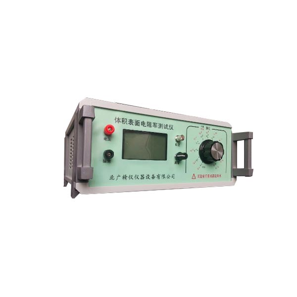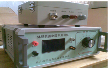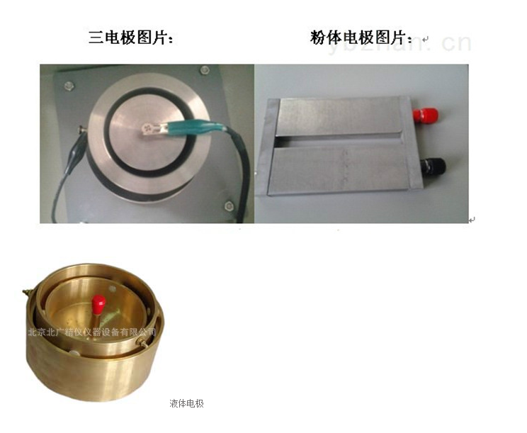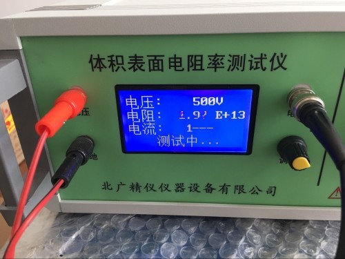
体积表面电阻率测试仪北京厂家 工作原理
根据欧姆定律,被测电阻Rx等于施加电压V除以通过的电流I。BEST121型数字高阻计是同时测出电阻两端的电压V和流过电阻的电流I,通过内部的大规模集成电路完成电压除以电流的计算,然后把所得到的结果经过A/D转换后以数字显示出电阻值,即便是电阻两端的电压V和流过电阻的电流I是同时变化,其显示的电阻值不象普通高阻计那样因被测电压V的变化或电流I的变化而变,所以,即使测量电压、被测量电阻、电源电压等发生变化对其结果影响不大,其测量精度很高,从理论上讲其误差可以做到零,而实际误差可以做到千分之几或万分之几。
体积表面电阻率测试仪北京厂家 典型应用
1.硫化橡胶体积、表面电阻率测定
2.测量防静电鞋、导电鞋的电阻值
3.测量防静电材料的电阻及电阻率
4.测量计算机房用活动地板的系统电阻值
5.测量绝缘材料电阻(率)
6.光电二极管暗电流测量
7.物理,光学和材料研究
8.高分子材料表面体积电阻率测定
安全注意事项
1.使用前务必详阅此说明书,并遵照指示步骤,依次操作。
2.请勿使用非原厂提供之附件,以免发生危险。
3.进行测试时,本仪器测量端高压输出端上有直流高压输出,严禁人体接触 ,以
免触电。
4.为避免测试棒本身绝缘泄漏造成误差,接仪器测量端输入的测试棒应尽可 能悬
空,不与外界物体相碰。
5.当被测物绝缘电阻值高,且测量出现指针不稳现象时,可将仪器测量线屏 蔽端夹子接 上。 例如: 对电 缆测缆 芯与 缆壳的 绝缘 时,除 将被 测物两 端分 别接于 输入 端与高压 端, 再将电 缆壳 ,芯之 间的 内层绝 缘物 接仪器 “G”,以消 除因 表面漏 电而 引起的测 量误 差。也 可用 加屏蔽 盒的 方法, 即将 被测物 置于 金属屏 蔽盒 内,接 上测 量线。
技术指标
序号 项目 参数
1 电阻测量范围 0.01?104Ω~1?1018Ω
2 电流测量范围为 2?10-4A~1?10-16A
3 双表头显示 3.1/2位LED显示
4 内置测试电压 100V、250V、500V、1000V
5 基本准确度 1% (*注)
6 内置测试电压 100V、250、500、1000V
7 使用环境 温度:0℃~40℃相对湿度<80%
8 供电形式 AC 220V,50HZ,功耗约5W
9 仪器尺寸 285mm?245mm?120 mm
10 质量 约2.5KG
符合标准
GB/T 1410-2006、GB 12014、GB/T 20991-2007、GB 4385-1995、GB 12158-2006、GB 4655-2003、GB/T 12703.4-2010、GB/T 12703.6-2010、GB 13348-2009、GB/T 15738-2008、GB/T 18044-2008、GB/T 18864-2002、GB/T 22042-2008、GB/T 22043-2008、GB/T 24249-2009、GB 26539-2011、GB/T 26825-2011、GB 50515-2010、GB 50611-2010、GJB 105-1998-Z、GJB 3007A-2009、GJB 5104-2004
温度影响
温度对不同物质的电阻值均有不同的影晌。
导电体在接近室温的温度,良导体的电阻值,通常与温度成线性关系:
ρ=ρ0(1 αt)
上式中的a称为电阻的温度系数。
未经掺杂的半导体的电阻随温度升高而下降:
有掺杂的半导体变化较为复杂。当温度从绝对零度上升,半导体的电阻先是减少,到了绝大部分的带电粒子(电子或电洞/空穴) 离开了它们的载体后,电阻会因带电粒子的活动力下降而随温度稍为上升。当温度升得更高,半导体会产生新的载体 (和未经掺杂的半导体一样) ,原有的载体 (因渗杂而产生者) 重要性下降,于是电阻会再度下降。
绝缘体和电解质绝缘体和电解质的电阻与温度的关系一般不成比例,而且不同物质有不同的变化,故不在此列出概括性的算式。
测试电压(V)
DC—10V
DC—50V
DC—100V
DC—500V
DC—1000V
标准配置:
1、仪器主机 一台
2、屏蔽箱一个
3、试验电极三个
4、说明书一本
5、电源线一条
6、数据线三条
7、合格证一份
8、保修卡一份
意义
1通常,绝缘材料用于将电气系统的各部件相互绝缘和对地绝缘;固体绝缘材料还起机械支撑作用。
对于这些用途,一般都希望材料具有尽可能高的绝缘电阻,有均匀一致的、得到认可的机械、化学和耐热
性能。表面电阻随湿度变化很快,而体积电阻随温度变化却很慢,尽管其终的变化也许较大
2体积电阻率能被用作选择特定用途绝缘材料的一个参数。电阻率随温度和湿度的变化而显著变
化,因此在为一些运行条件而设计时必须对其了解。体积电阻率的测量常被用于检查绝缘材料生产是
否始终如一,或检测能影响材料质量而又不能用其他方法检测到的导电杂质
3 一直流电压加在与试样相接触的两电极之间时,通过试样的电流会渐近地减小到一个稳定值。
电流随时间的减小可能是由于电介质极化和可动离子位移到电极所致。对于体积电阻率小于
loll n"m的材料,其稳定状态通常在一分钟内达到,因此,经过这个电化时间后测定电阻。对于体积电
阻率较高的材料,电流减小的过程可能会持续到几分钟、几小时、几天甚至几星期。因此对于这样的材
料,采用较长的电化时间,且如果合适,可用体积电阻率与时间的关系来描述材料的特性.
4由于或多或少的体积电导总是要被包括到表面电导测试中去,因此不能精确而只能近似地测量表
面电阻或表面电导。测得的值主要反映被侧试样表面污染的特性。而且试样的电容率影响污染物质的
沉积,它们的导电能力义受试样的表面特性所影响。。因此,表面电阻率不是一个真正意义的材料特性,
而是材料表面含有污染物质时与材料特性有关的一个参数。
某些材料如层压材料在表面层和内部可能有很不同的电阻率,因此测量清洁的表面的内在性能是
有意义的。应完整地规定为获得一致的结果而进行清洁处理的程序,并要记录清洁过程中溶剂或其他
因素对于表面特性可能产生的影响。
表面电阻,特别是当它较高时,常以不规则方式变化,且通常非常依赖于电化时间。因此,测量时通
常规定一分钟的电化时间。
注意事项
绝缘电阻仪器体积电阻表面电阻测试仪使用前请仔细阅读以下内容,否则将造成仪器损坏或电击情况。
1.◇检查仪器后面板电压量程是否置于10V档,电流电阻量程是否置于104档。
2.◇接通电源调零,(注意此时主机不得与屏蔽箱线路连接)在“Rx”两端开路的情况下,调零使电流表的显示为0000。然后关机。
3.◇将待测试样平铺在不保护电极正中央,然后用保护电极压住样品,再插入被保护电极(不保护电极、保护电极、被保护电极应同轴且确认电极之间无短路)。
4.◇测体积电阻时测试按钮拨到Rv边,测表面电阻时测试按钮拨到Rs边,
5.◇接好测试线,将测试线将主机与屏蔽箱连接好。量程置于104档,打开主机后面板电源开关按钮。从仪器后面板调电压按钮到所要求的测量电压。(比如:GBT 1692-2008硫化橡胶 绝缘电阻率的测定 标准中注明要求在500V电压进行测定,那么电压就要升到500V)
6.◇电流电阻量程按钮从低档位逐渐拨高档,每拨一次停留1-2秒观察显示数字,当被测电阻大于仪器测量量程时,电阻表显示“1”,此时应继续将仪器拨到量程更高的位置。测量仪器有显示值时应停下,在1min的电化时间后测量电阻,当前的数字乘以档次即是被测电阻。
7.◇测试完毕先将量程拨至(104)档,然后将测量电压拨至10V档, 后将测试按钮拨到中央位置后关闭电源。然后进行下一次测试。

8.◇应在“Rx”两端开路时调零,一般一次调零后在测试过程中不需再调零。
9.◇禁止将“RX”两端短路,以免微电流放大器受大电流冲击。
10.◇不得在测试过程中不要随意改动测量电压。
11.◇测量时从低次档逐渐拨往高次档。
12.◇接通电源后,手指不能触及高压线的金属部分。
13.◇不得测试过程中不能触摸微电流测试端。
14.◇在测量高阻时,应采用屏蔽盒将被测物体屏蔽。
15.◇严禁在试测过程随意改变电压量程及在通电过程中打开主机。
16.◇严禁电流电阻量程未在104档及电压在10V档,更换试样。
working principle
According to Ohm's Law, the measured resistance Rx is equal to the applied voltage V divided by the current I passing through. The BEST121 digital high resistance meter simultaneously measures the voltage V across the resistor and the current I flowing through the resistor. It calculates the voltage divided by the current through an internal large-scale integrated circuit, and then displays the resistance value digitally after A/D conversion. Even if the voltage V across the resistor and the current I flowing through the resistor change at the same time, the displayed resistance value does not change due to changes in the measured voltage V or current I like ordinary high resistance meters. Therefore, even if there are changes in the measured voltage, measured resistance, power supply voltage, etc. that have little impact on its results, its measurement accuracy is very high. Theoretically, its error can be zero, while the actual error can reach a few thousandths or tens of thousands.
Typical applications
1. Determination of volume and surface resistivity of vulcanized rubber
2. Measure the resistance value of anti-static shoes and conductive shoes
3. Measure the resistance and resistivity of anti-static materials
4. Measure the system resistance value of the raised floor used in the computer room
5. Measure the resistance (rate) of insulation materials
6. Measurement of dark current in photodiodes
7. Physics, optics, and materials research
8. Measurement of surface volume resistivity of polymer materials
Safety precautions
1. Before use, be sure to read this manual carefully and follow the instructions in sequence.
2. Do not use accessories not provided by the original factory to avoid danger.
During testing, there is a DC high voltage output on the high voltage output terminal of the measuring end of this instrument. It is strictly prohibited for human contact
No electric shock.
To avoid errors caused by insulation leakage of the test rod itself, the test rod connected to the measuring end of the instrument should be suspended as much as possible
Empty, not colliding with external objects.
When the insulation resistance value of the measured object is high and the pointer is unstable during measurement, the shielding end clamp of the instrument measurement line can be connected. For example, when measuring the insulation between the cable core and the cable shell, in addition to connecting the two ends of the measured object to the input end and the high voltage end respectively, the inner insulation between the cable shell and core is connected to the instrument "G" to eliminate measurement errors caused by surface leakage. Alternatively, the method of adding a shielding box can be used, which involves placing the object under test in a metal shielding box and connecting the measuring wire.
Technical indicators
Number Project Parameters
1. Resistance measurement range 0.01?104Ω~1?1018Ω
The current measurement range is 2?10-4A to 1?10-16A
3 Dual Header Display 3.1/2 LED Display
Built in testing voltages of 100V, 250V, 500V, and 1000V
5 basic accuracy 1% (* note)
6 built-in test voltages of 100V, 250, 500, 1000V
7. Operating environment temperature: 0℃~40℃, relative humidity<80%
8 power supply form AC 220V, 50HZ, power consumption of about 5W
9 Instrument dimensions 285mm?245mm?120mm
10 mass approximately 2.5KG
Compliant with standards
GB/T 1410-2006、GB 12014、GB/T 20991-2007、GB 4385-1995、GB 12158-2006、GB 4655-2003、GB/T 12703.4-2010、GB/T 12703.6-2010、GB 13348-2009、GB/T 15738-2008、GB/T 18044-2008、GB/T 18864-2002、GB/T 22042-2008、GB/T 22043-2008、GB/T 24249-2009、GB 26539-2011、GB/T 26825-2011、GB 50515-2010、GB 50611-2010、GJB 105-1998-Z、GJB 3007A-2009、GJB 5104-2004
Temperature influence
Temperature has different effects on the resistance values of different substances.
At temperatures close to room temperature, the resistance value of a good conductor is usually linearly related to temperature
ρ=ρ0(1 αt)
The 'a' in the above equation is called the temperature coefficient of resistance.
The resistance of undoped semiconductors decreases with increasing temperature:
The changes in doped semiconductors are more complex. When the temperature rises from absolute zero, the resistance of the semiconductor first decreases, and after the majority of charged particles (electrons or holes/holes) leave their carriers, the resistance slightly increases with temperature due to the decrease in the activity force of the charged particles. When the temperature rises higher, semiconductors will produce new carriers (like undoped semiconductors), and the importance of the original carriers (generated due to doping) will decrease, resulting in a further decrease in resistance.
The relationship between the resistance of insulators and electrolytes and temperature is generally not proportional, and different substances have different changes, so a general formula is not listed here.
Test voltage (V)
DC—10V
DC—50V
DC—100V
DC—500V
DC—1000V
Standard configuration:
1. One instrument host
2. One shielding box
3. Three experimental electrodes
4. One manual
5. One power cord
6. Three data cables
7. One certificate of conformity
8. One warranty card
significance
Usually, insulation materials are used to insulate the various components of an electrical system from each other and from the ground; Solid insulation materials also serve as mechanical support.
For these applications, it is generally desirable for materials to have the highest possible insulation resistance, with uniform and recognized mechanical, chemical, and heat resistance
Performance. The surface resistance changes rapidly with humidity, while the volume resistance changes slowly with temperature, although its final change may be significant
Volume resistivity can be used as a parameter for selecting insulation materials for specific applications. The resistivity changes significantly with temperature and humidity
Therefore, it is necessary to understand it when designing for certain operating conditions. The measurement of volume resistivity is often used to check the production of insulation materials
Whether it is consistent or detecting conductive impurities that can affect material quality but cannot be detected by other methods
When a DC voltage is applied between the two electrodes in contact with the sample, the current passing through the sample will asymptotically decrease to a stable value.
The decrease in current over time may be due to dielectric polarization and the displacement of movable ions to the electrode. For volume resistivity less than
The material of loll n "m usually reaches a stable state within one minute, so the resistance is measured after this electrification time. For volume electricity
The process of reducing current in materials with high resistivity may last for several minutes, hours, days, or even weeks. Therefore, for such materials
Material, using a longer electrochemical time, and if appropriate, the relationship between volume resistivity and time can be used to describe the characteristics of the material
Due to the fact that more or less volume conductivity is always included in surface conductivity testing, it cannot be accurately measured and can only be approximately measured
Surface resistance or surface conductivity. The measured values mainly reflect the characteristics of surface contamination of the side sample. Moreover, the capacitance of the sample affects the contamination of the substance
Sedimentation, their conductivity is influenced by the surface characteristics of the sample.. Therefore, surface resistivity is not a true material property,
But it is a parameter related to the material properties when the surface of the material contains pollutants.
Some materials, such as laminates, may have very different electrical resistivity in the surface layer and interior, so measuring the intrinsic properties of a clean surface is important
meaningful. The procedure for cleaning to achieve consistent results should be fully defined, and the solvents or other substances used during the cleaning process should be recorded
The possible impact of factors on surface characteristics.
Surface resistance, especially when it is high, often changes irregularly and is often highly dependent on electrochemical time. Therefore, during measurement, communication is necessary
Regularly set a one minute electrification time.
matters needing attention
Before using the insulation resistance instrument, volume resistance surface resistance tester, please carefully read the following content, otherwise it may cause damage to the instrument or electric shock.
1.◇Check if the voltage range on the back panel of the instrument is set to 10V and if the current resistance range is set to 104.
2.◇Connect the power and zero it (note that the host should not be connected to the shielding box circuit at this time). In the case of an open circuit at both ends of "Rx", zero it to display 0000 on the ammeter. Then shut down.
3. Lay the test sample flat in the center of the unprotected electrode, then press the sample with the protective electrode, and insert the protected electrode (the unprotected electrode, protective electrode, and protected electrode should be coaxial and confirm that there is no short circuit between the electrodes).
When measuring volume resistance, turn the test button to the Rv side, and when measuring surface resistance, turn the test button to the Rs side,
5. Connect the test cable and connect the host to the shielding box. Set the range to 104 and turn on the power switch button on the back panel of the host. Adjust the voltage button on the back panel of the instrument to the required measurement voltage. (For example, in the GBT 1692-2008 standard for measuring the insulation resistivity of vulcanized rubber, it is specified that the measurement should be carried out at a voltage of 500V, so the voltage should be raised to 500V.)
6.◇Gradually shift the current resistance range button from low to high, and hold for 1-2 seconds each time to observe the displayed number. When the measured resistance is greater than the instrument's measurement range, the resistance meter will display "1". At this time, continue to move the instrument to a higher range position. When the measuring instrument displays a value, it should stop and measure the resistance after 1 minute of electrification time. The current number multiplied by the level is the measured resistance.
After the test is completed, first set the range to (104), then set the measured voltage to 10V, and finally turn off the power after setting the test button to the center position. Then proceed to the next test.
8. It should be zeroed when there is an open circuit at both ends of "Rx". Generally, after one zeroing, there is no need to zero again during the testing process.
9.◇It is forbidden to short-circuit the "RX" at both ends to prevent the microcurrent amplifier from being impacted by high currents.
10.◇Do not arbitrarily change the measured voltage during the testing process.
11. During measurement, gradually shift from low gear to high gear.
After connecting the power supply, fingers should not touch the metal parts of the high-voltage line.
13.◇Do not touch the microcurrent testing terminal during the testing process.
When measuring high resistance, a shielding box should be used to shield the object being measured.
15.◇It is strictly prohibited to change the voltage range arbitrarily during the testing process and to turn on the host during the power on process.
16.◇It is strictly prohibited to replace the sample if the current resistance range is not in the 104 range and the voltage is in the 10V range.
业务咨询:932174181 媒体合作:2279387437 24小时服务热线:15136468001 盘古机械网 - 全面、科学的机械行业免费发布信息网站 Copyright 2017 PGJXO.COM 豫ICP备12019803号